Two Stroke Engine With A
Dedicated Crank Oil System And Variable�Ram Blower:
Double-click on any of these links to see all four of the inventor's products
���
��
���


VR Powerstroke Description:
This is a two stroke engine that runs off gas. No oil mix is required.
The reason it does not require an oil mix is because it has a dedicated
lubrication system for the crankcase, unlike other existing two stroke engines.
The advantages include:
1. Low cost and simplicity of manufacturing. It is less expensive to produce
than a four stroke, as it has less moving parts, no conventional valves and
overall less construction material.
2. Less pollution than the existing two stroke that runs off a gas/oil mix,
which causes burning oil and fuel to escape out of the exhaust port and is thus
harmful to the environment.
3. Less weight than a gas driven four stroke, and an overall better power to
weight ratio.
4. Higher efficiency of burning fuel because of the constant air intake pressure
and volume to the cylinder for optimal combustion.
5. Will operate at higher RPM�s than a four stroke because there are no
conventional valves.
6. This particular two stroke engine has more power than either engine. The four
stroke has only one power stroke out of four strokes. Further it has a longer
compression stroke and power stroke than a two stroke due to the open exhaust
port on the existing two stroke engine.
7. Due to the fact that this engine has a dedicated lubrication system we are
not adding oil to the fuel mixture, therefore the likelihood of addressing a
clogged carburetor or fuel system is virtually eliminated.
8. The prior art two stroke engine is composed of a gas-oil mixture for
operation. This two stroke engine is not as expensive to operate because it has
a dedicated lubrication system and eliminates the need for two stroke oil.
SUMMARY
It is an object of the present invention to provide a two stroke engine with a
variable fan that is used to provide compressed air to the engine, which allows
oil to be supplied directly to the crankcase and separate it from the fuel. The
engine cylinder is purged with fresh air which is free of oil and exhaust gases
thus improving efficiency, fuel consumption, with an overall effect of extending
engine life. The present invention provides a two stroke engine with a rolling
valve plate that contains the engine�s main intake, purge and exhaust valves.
It is an object of the present invention to provide valves in the intake and
exhaust lines of this two-stroke engine to optimize its performance. The
separate fan or compressor in the present invention eliminates the need for
adding oil to the fuel, clearly making lubrication less of a problem. The intake
and exhaust gases are passed through a unique rolling valve plate, allowing
custom valve openings to optimize engine performance.
DETAILED DESCRIPTION OF THE INVENTION
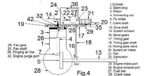
Figure 4 is a cross sectional/schematic invention which shows the basic engine
parts including a cylinder 1, a piston 3, a connecting rod 4, an engine flywheel
5, a crankshaft 7, a system air intake port 20, a fan, blower or compressor 21,
a rolling valve plate 19 which includes the engine�s intake valve 31 and
exhaust valve 30, (shown in Figure 5) a carburetor 22 and a system exhaust port
14. The principal component differences between the present invention and the
prior art, are the addition of the fan 21 and the elimination of the bypass and
the air-fuel-oil input port. A principal operating difference between the
present invention and the prior art is the air-fuel mixture produced in the
carburetor is injected under pressure from the fan directly into the cylinder
head to eliminate the need to compress this mixture in the crankcase or feed it
through the bypass to the cylinder head of the prior art. In the present
invention, the fan 21 is added and is driven by a mechanical linkage to the
engine crankshaft. The linkage comprises the fan shaft 35, the fan gear 29, the
timing gear 17, and beveled gears 16. Fan 21 takes in outside air, through
system intake port 20 compresses it and then supplies it through a line 23,
carburetor 22, line 24 and rolling intake valve 31 to the cylinder head, which
is port 42. The exhaust path from the engine is also through the rolling exhaust
valve 30, which is located on rolling plate 19, to the systems exhaust port 14.
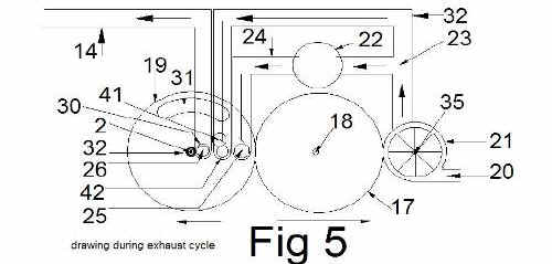
The rolling valves are a unique feature of this invention and are explained in
more detail in connection with the description of Figure 5. As can be seen in
Figure 5, the rolling plate 19 contains the input port 31 and the exhaust port
30. This plate is caused to rotate by way of a power take off from the drive
shaft 13. The drive shaft is connected to the flywheel and derives its relative
power from the engine. The power take off is shown in Figure 4 to be a set of
bevel gears 16 connecting a timing gear shaft 18 to the drive shaft. The timing
gear shaft 18 is connected at its upper end to the timing gear 17. The rotation
of the drive shaft causes the timing gear shaft and the timing gear to rotate.
The outer edge of the timing gear contains gear teeth which mesh with mating
gear teeth of the outer edge of the rolling valve plate 19, causing it to
rotate. The timing gear is connected to the drive shaft 13 by way of shaft 18
and bevel gears 16, causing the timing gear to rotate as a function of the
engine speed. That arrangement forces the timing gear and the plate 19 to be at
a known position with respect to the values at each point in the engines cycle,
admitting purging air and the air fuel mixture when required.
�
�
Please
visit the
inventor's three other products on this site:
Inventor:� Terra Projects, Inc.
E-mail:� [email protected]
Phone:� (772) 621-8187
Cell:� (678) 794-5657